When replacing the damaged rolling bearing, it can be disassembled with screw type pulling tool, or the bearing inner sleeve or outer sleeve can be pressed out with a press. For the pulling out or pressing out of the bearing, attention should be paid to the point of force acting evenly on the inner sleeve of the bearing, and the direction of the force should be parallel to the axial center; it is not allowed to let the bearing sleeve move out of the transmission shaft in an inclined way, so as to avoid the bearing sleeve damaging the working surface of the transmission shaft.
The installation method of rolling bearing is decided by the size of interference between bearing and mating shaft. When the minimum size of interference is small, it can be assembled by hammering. When striking with a hand hammer, attention should be paid to the point of exertion, and the force should be uniform; the bearing matched with the shaft should hit the inner sleeve; the shaft sleeve matched with the bearing seat should hit the outer sleeve.

If the interference between the bearing sleeve and the mating shaft is large, the sleeve can be used to assemble the bearing. Then according to the size of the interference, the hammer is used to hit or the press is used to assemble. Large bearings or bearings with large interference size can also be assembled by oil bath heating method. Hang the bearing in 80-100 ℃ oil, heat it at constant temperature for a period of time, take it out, and immediately assemble it on the shaft.
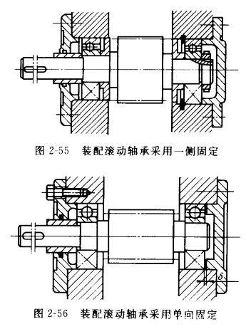
When assembling the rolling bearing, no matter what kind of fitting form is adopted, attention should be paid to the axial displacement during operation. This displacement is due to the thermal expansion caused by the temperature rise when the bearing works. If the axial displacement is not left when the bearing is installed, the expansion force acts on the bearing, which will increase the working load of the bearing and accelerate the wear of the bearing. The assembly of bearing in Fig. 2-55 shows that the right side controls the bearing to move in both directions, while the left side leaves a gap between the bearing and the gland. The bearing assembly in fig.2-56 is that the left side of the bearing outer sleeve is fixed, and the right side has a certain moving clearance, while there is no fixed limit on both sides of the inner sleeve